Click the radio button to add to a database, and click on the folder to navigate to the database, feature dataset and empty annotation feature class to which you wish to add the annotation.
Click the new Convert Coverage Annotation icon, and a dialog box opens asking to select the annotation layer to convert. Once the tool has been added to a toolbar, close the Customize dialog box. 
Left-click the tool icon and, holding down the left mouse button, drag it into a toolbar displayed in your ArcMap window. In the Commands list, note the Convert Coverage Annotation tool. On the Commands tab, select Label from the Categories list. In ArcMap, click Customize > Customize Mode.After creating the new annotation feature class, close the ArcCatalog window.In the final dialog where the attribute fields are listed, if you want the attributes from the CAD annotation included in the geodatabase annotation feature class, click the Import button, navigate to the CAD annotation feature class, select it, and click Add. The attributes from the CAD annotation are added to the geodatabase feature class.For example, the scale in ArcMap may be 1:1200. Enter the scale value into the Reference Scale box in the New Feature Class dialog in ArcCatalog.Give the new annotation feature class a name, and click Next through the subsequent dialogs.
 Right-click the feature dataset, and select New > Feature Class. This will contain the annotation. Open the ArcCatalog window, and navigate to the geodatabase that contains the point, polyline polygon and multipatch features from the CAD file. The reference scale should be set to a map scale which is typical for the data, either for plotting or on-screen display. Once the reference scale is set for the new annotation feature class in the geodatabase, it cannot be changed. Zoom in to the annotation until in the screen display of the annotation is rendered at a suitable size for viewing or printing. On the General tab, set the map and display units to the units in which the data was created, for example, feet, meters or other units. To determine an appropriate reference scale for the annotation, open a new, empty map in ArcMap, and draw the CAD annotation. This method preserves font, text size and text color. Click OK. The feature types selected are imported to the feature dataset in the geodatabase. Importing annotation by this method creates another point feature class, with each point at the anchor point for the annotation string. The annotation string is preserved in the TextString field in the geodatabase feature class. Double-click the CAD file to open, and select Point, Polyline, Polygon and Multipatch feature classes. Right-click the feature dataset, and select Import > Feature Class (multiple) and browse to the CAD file. Create a new file geodatabase, then right click on the geodatabase, and create a new feature dataset, defining the projection to match the coordinate system in which the CAD data was created. These alternative steps preserve the font used to create the text, as well as the color and size of the original text entities from the CAD file. The features from the CAD file are imported to feature classes in the feature dataset.Īlternative instructions for importing the CAD annotation to the geodatabase are provided below.
  Click OK in the CAD to Geodatabase dialog. Select the projection in which the CAD data was created, or the custom projection created for the CAD file (as above). Set the Reference Scale for the CAD file. Instructions are provided below for determining an appropriate reference scale for the data. The name cannot contain spaces, although underscores can be used.
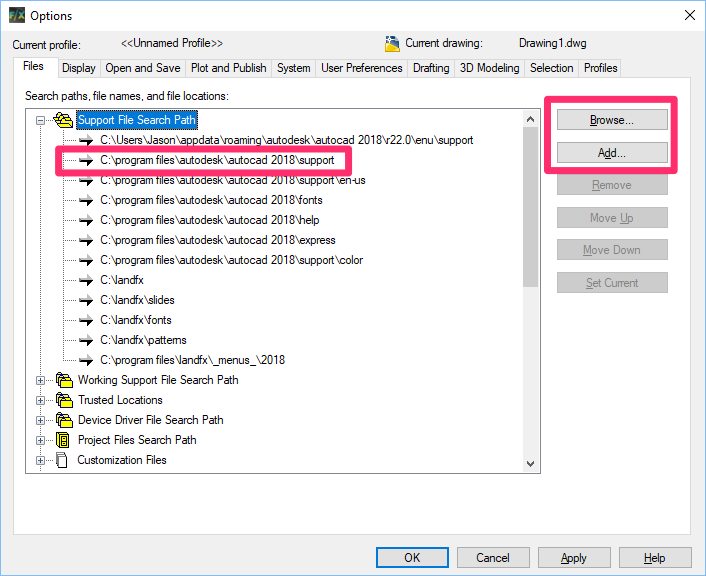
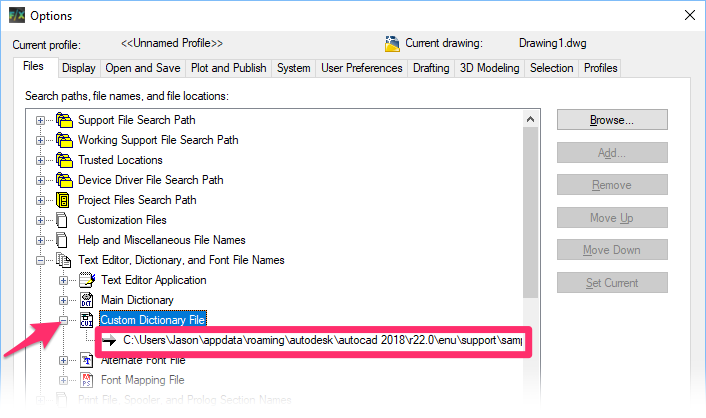
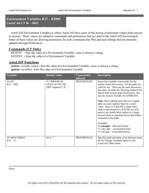
 AUTOCAD ENGLISH DICTIONARY FILE SOFTWARE
The software automatically creates a feature dataset in the default geodatabase to contain the data, although the name can be changed if desired. Browse to the CAD file on disk and select it as the input.Open ArcToolbox > Conversion Tools > To Geodatabase, and select CAD to Geodatabase.Open the ArcCatalog window from within ArcMap, right-click the new file geodatabase, and select Make Default Geodatabase.If possible create the new file geodatabase on the local hard drive. Rename the file geodabase if desired, but the.
 In ArcCatalog, create a new file geodatabase to contain the CAD features by right-clicking the folder where the file geodatabase will reside > New File Geodatabase. Refer to the following Knowledge Base article: How To: Identify the spatial reference, projection, or coordinate system of data See also the associated related articles for that procedure. Procedureīefore performing the following process, the projection for the CAD data must be defined. Instructions provided describe the steps to convert AutoCAD DWG files to a GIS-compatible file geodatabase. How To: Convert AutoCAD DWG files to a GIS-compatible file geodatabase Summary


 0 kommentar(er)
